Inside of a Wyze sprinkler controller

Well, I’ve been lazy on writing blogs, but that doesn’t mean I didn’t do things. I’m just not good at writing, or to be more specific, writing things are not code:)

Anyway, I think this is probably just a teardown log. I got a Wyze sprinkler controller long time ago, which is, well, right after I did the winterization of my irrigation system. So it’s been sitting there for quite some days. Now spring is getting closer, I think I need to hook it up. However, before I really put it in use, my curiosity is forcing me to get the evil screw driver, and, my credit card, of course, an expired one, just so that I can pry open something.

In short, here is how you open it and some pictures.

Open the case is quite easy: Unscrew the 2 screws from the back cover, and then you can pry open the front cover with a credit card, make sure you use the expired one:)

Once front cover is removed, there are 3 more screws to remove. That makes the PCB board completely off the back cover. Now you can see the entire thing inside:

I’m not surprised to see the ESP32 module in this device: You get the WiFi connectivity and also be able to pair with Bluetooth. ESP32 is the obvious choice.

I am, however, surprised that there is a LoRA module (Ra-01H) included. LoRA is good for long range, low speed wireless communications. It also consumes much less power than WiFi. Two possible usages coming into my mind:

  1. There are sensors supported, such as rain sensor, or soil moisture sensor. I don’t see Wyze mention any of these, but it’s quite possible.
  2. Wyze mentioned they have some partners doing precise weather forecast. Maybe they have some weather stations setup for every city so this thing can directly communication with those stations? I really doubt that, but this is another possibility.

There is also an STM32 micro controller, which I think is running the main logic, scheduling, LED control, etc. I’m surprised that they don’t run these logics on the ESP32. It should be more than capable of doing all the controls. I think one thing ESP32 is not good for this is to have enough GPIOs to control all the valves and all the LEDs.

Anyway, I’m wondering if there is anything I can try with this. There are programming headers for both the STM32 and ESP32. So in theory I should be able to dump the current firmware and flash my own. Hmm, I guess I will keep my current sprinkler controller for more time while playing around with this one.

Btw, I think I know why I’m lazy on writing blogs: the editor of wordpress is terrible to use. Does anyone know a good editor for this kind of things?

Posted in Uncategorized | 3 Comments

Tearing down a Costco remote ceiling light

I was so tired of getting out of bed to turn on/off the ceiling light in my bedroom. So one day when I saw Costco was selling a remote controlled led ceiling light, I immediately grabbed one:

There was nothing special for the installation: You unscrew the old ceiling light, put the new one on, hook up the mains wire using the provided wire nuts. Of course I turned off the switch and double checked the power was off so I don’t get electrocuted.

However, before I hooked up, I think I should take a look at what’s inside: The text printed on the box and the remote controller indicate it has some fancy functionalities:

  • Adjustable brightness
  • Adjustable color temperature
  • Ambient light sensor
  • Motion sensor with adjustable sensitivity
  • Automatically turning off after a couple minutes

That’s quite a lot of things and I’d like to see how it’s implemented. Tearing this thing apart is probably the easiest thing I ever had. So here are the pictures of its internal:

IMG_20190715_224314IMG_20190715_215436IMG_20190715_213434

Of course there are LEDs. They are mounted on a PCB. There is nothing fancy with that so I didn’t take a picture of it. Behind the PCB there are only two parts: A power adapter, and a controller unit.  The controller unit has two sets of wires: One set goes into the controller unit, and the other set connects to the LED plate.

It’s quite simple but one thing really surprised me: The controller unit has an FCCID on it! For anyone being interested into RF and electronics, you probably know that FCCID means it’s emitting some sorts of radio frequency, which is not mentioned on the user manual at all. Hmm, of course I did a quick search on google with FCCID WUI-LM561232 and here is it:

Microwave Sensor Module

So unlike what I thought using a PIR sensor for motion detection, it’s using microwave! I’ve seen a youtube video from Andreas Spiess talking about radar sensors , I think this one is similar. What’s also very interesting is this one operates at “5.75-5.856 GHz” range, which may have some overlap with 5G wifi bands — no wonder in the review section someone says this light was interfering with his wifi — although i didn’t have this issue with it.

To satisfy my curiosity, I pried open the controller unit and here is how it looks:

img_20191125_214922.jpg

On the top is an antenna for the sensor module. It’s connected to the main controller board using some header connectors. So I have to bend the headers to reveal what’s under it.

IMG_20190715_213154img_20190715_213326.jpg

As you can see in the sensor is entirely enclosed in a metal can, which is a common practice for shielding. The sensor connects to the main board with 3 pins, VCC, GND, and Signal — I have no idea how it adjusts the sensitivity of the motion sensor with these pins.

On the main board, there are a couple components. The larger IC is the micro-controller Nuvoton n76e003at20, which is responsible for the main controlling logic. The smaller 8-pin IC has a marking “2904 MZ2812” but I couldn’t find any information about that. Other than those, there are three LED like things, the dark one is the IR receiver, the green one is an LED indicator, the white one I think it’s a ambient light sensor.

It’s not easy to see on the picture, but with a closer look, I can tell the white header has 4 pins, which are GND, 5V, PWM1, PWM2. It’s basically the controller receives 5V power, and then it outputs two PWM signals, controlling the strength of two sets of LEDs with 5K and 3K color temperature.

OK, that’s all about the tear-down. The moment I saw the insides of this ceiling lights, I went to Costco again and bought a couple more. Why? Because this looks like a perfect candidate for a hobby project: it should be very easy to convert this into a internet connected ceiling light without messing up with mains voltage. If i’m going to do that, I want all my bedrooms using this model.

Posted in Electronics, IOT | 6 Comments

How to ignore Python3 stdin encoding error?

I was writing some quick and dirty python script to parse output of another command line application. So here is what I had:

#!/usr/bin/env python3

import sys

for line in sys.stdin:
    print("RECEIVED:" + line.rstrip())

Of course you will run into the following problem occasionally:

XXX:~$ printf "AAA\xC0BBB" | ./foo.py 
Traceback (most recent call last):
  File "./foo.py", line 9, in <module>
    for line in sys.stdin:
  File "/usr/lib/python3.7/codecs.py", line 322, in decode
    (result, consumed) = self._buffer_decode(data, self.errors, final)
UnicodeDecodeError: 'utf-8' codec can't decode byte 0xc0 in position 0: invalid start byte

Well, i know that character is not a valid utf-8 sequence, but I don’t care. Can you please ignore it, shut up and continue instead of abort the process?

I think this is a common request but it actually took me quite a while to figure out the solution:

From python 3.7, you should be able to “Reconfigure this text stream using new settings for encoding, errors, newline, line_buffering and write_through.”

So all you need is to reconfigure it with “errors” set to “ignore”, or anything you prefer.

#!/usr/bin/env python3

import sys

sys.stdin.reconfigure(errors='ignore')

for line in sys.stdin:
    print("RECEIVED:" + line.rstrip())

And this is the output you will get with that fix:

XXX:~$ printf "AAA\xC0BBB" | ./foo.py 
RECEIVED:AAABBB


Posted in Computer and Internet, programming, Python | Leave a comment

WyzeCam without SD card?

Disclaimer:

I’m doing this purely for fun. I have no guarantee this will work for you. It may brick your wyze camera, void your warranty or cause other damages. So do this at your own risk and don’t blame on me if bad things happen.

What else do you usually put into your shopping cart when you buy a Wyze Camera? Yep, an SD card. Wyze camera provides great cloud service, which includes uploading 12 seconds of motion clips onto AWS for free. However, it’s always good to put an SD card into the camera, so you get local recordings, and other features such as timelapse, etc. Some people also prefer continuous recording on SD card so you can always review what happened in last couple days.

However, there are some issues with SD card:

  1. Capacity: I didn’t try but searching around with google says the maximum SD card capacity Wyze camera support is 32GB. That sounds like a lot, but if you do continuous recording, it can quickly run out. Luckily there is loop recording feature, which means older recordings will be deleted so you will end up only a couple days recordings.
  2. Durability: In additional to capacity, durability is also a big concern if you are doing continuous recording. I’ve heard and experienced many instances that the SD card gets corrupted after some period. The last thing you want is finding out all the recordings on the SD card are not readable when something bad happened.
  3. Accessibility: Sure you can use the app to view the recordings, but it’s not very convenient to scroll in that small timeline. So you end up unplug the SD card, and copying all your recordings onto your computer. But that doesn’t work out very well if you need to do this every couple days, or if you need to access a camera mounted high.
  4. Data safety: If you are using wyze camera as security cameras, and relying on the recordings on the SD card. An intruder can easily grab your camera and then you lose everything, except the 12 second cloud recording.
  5. Cost: With the technology getting more advanced, the cost of the SD card is no longer such a big deal. However, consider that the camera only cost $20, a $10 SD card is still a significant portion of the overall cost.

Because of all the above reasons, there are always feature request about supporting alternative storage solutions, such as network share, etc. As a result, Wyze also published the separate RTSP firmware, which, partially addressed this issue.  But, by using the RTSP firmware, I believe (didn’t try) you also lose some features provided by the main firmware.

I’ve been using and studying Wyze camera for quite a while and I’m amazed on what you can do with this little thing. So today, i’m going to present my solution to the SD card, without sacrificing any of the wyze features.

First, let me show you a picture:

20190716234946

See the capacity of my SD card? Of course there is no such SD card (well, there may be, but definitely not affordable to me…). So here is how I made it…

The work involves tearing apart a wyze camera, soldering UART cables, and openning TTY consoles, looking into it’s firmware, and logging, etc. It’s a long story but I will try to make it short:

  1. Wyze camera runs on an embedded Linux system. This means there are common Linux features, such as shell, kernel, file system, etc. The Wyze camera’s primary functionality is provided by an userspace executable named iCamera.
  2. Wyze camera does no signature check on it’s firmware. This is good for DIYers, because that means you can make your own modifications to the firmware, or even creating completely different firmware, and easily run it on the hardware.
  3. When started, the iCamera will create a dedicated thread, checking if the SD card is inserted or not. If it’s found, it will mount the SD card, using the standard Linux “mount” command.
  4. The SD card is mounted to “/media/mmcblk0p1” (assuming you don’t have any other removable storage, and there is only one partition on the SD card). Once mounted, a local recording thread will start recording clips.
  5. Surprisingly, the local recording is not directly saved onto the sd card. Instead, it’s recorded under /tmp, which is a temporary file system backed by RAM. The recording last for one minute, exactly.
  6. Once the one minute recording is done, the recording thread will do a “cp” command, copying the recording to SD card, based on the timestamp. If you are doing continuous recording, that happens for the clip of every minute; if you are doing event only, then the copy will only happen if there was a motion event in last minute.
  7. The recording thread also checks the capacity of the SD card using “df” command from time to time. So if the free space is less than 60% (or something), it will start enumerate all the files, and removing the oldest ones till there is enough free space.
  8. By randomly checking around, I found the kernel by default support NFS, which is a linux network based file system (similar to windows file sharing service).

OK, so here is my idea:

  1. First I don’t want patch the binary of iCamera, which may disrupt Wyze’s builtin features.
  2. I can manually mount NFS share to “/media/mmcblk0p1”. However, this doesn’t work, because wyse won’t start recordings, if there is no SD card insertion detected.
  3. I noticed in latest firmware, Wyze checks the existence of /dev/mmcblk0 and /dev/mmcblk0p1 as an indication of SD card present. So all I need is “touch” these two files after I mount the NFS share.
  4. Well, that sort of worked, but Wyze will try to mount the SD card which of course will fail, causing the entire thing not work.
  5. I noticed Wyze is doing the mount operation by simply calling “mount” command. So, i just throw in a shell script, name it “mount” into one of the folder in the system path environment. Wyze will happily run that, instead of the real “mount” tool. In the script, i simply returns “success”.
  6. Now I heard the nice beep sound which usually happens when you insert the physical card, and the recording works!
  7. Since wyze is using “df” command to check the free space, i’m getting something like “2 terabytes” from the phone app, which is the size of my NAS disk.

OK, so prototyping works. But there is one more question:

I did all this from the serial console, which you can only get by physically opening the camera and soldering some wires. Not even as convenient as using actual SD card. I need something easier without breaking my hardware. That took a bit longer until I found two approaches:

  1. When Wyze is deleting old SD content, it’s using “rm -rf <dir_name>”. The “<dir_name>” comes from the SD card without sanitization.  So if I create a folder named “;telnetd”, it will happily run “rm -rf ;telnetd”, which, if you are familiar with Linux shell, starts a tool called “telnetd”.  So, to try it out, I picked a small SD card (1GB size), format it, and fill it all the way to its 60% capacity. And then created a directory called “/record/;telnetd”. A couple seconds after I inserted the SD card into camera, I found I can telnet into the camera.
  2. I was using the “deleting old SD content” method for quite a while, until later I found an easier one: Wyze support upgrading from SD card. So what you do is copying a firmware file named FIRMWARE_660R.bin, and a version.ini onto the root of the SD card. When you insert the SD card, it will apply the update. So what’s in FIRMWARE_660R.bin? After analyzing the code, the bin file is actually a .tar archive. When applying update, it will untar the archive, and then look for a special shell script, and run it! There is no signature checks! So this basically gives me arbitrary code executions. Nice!

So, i think I finally have something working without opening the physical hardware. Btw, once you have telnetd running, always run “echo 1>/configs/.Server_config” first. This command will create a flag file, which is used to tell the wyze firmware to always run telnetd when starting. So you don’t have to use the above tricks every time after you reboot your camera.

Well, it’s quite a lot text here. Sounds complicated, right? No worries, I packed everything together into an “easy-to-use” “WyzeHacks” github project. All you need is following the steps in the README file.

You can now run your wyze camera without SD cards, and have all the recordings directly saved onto your NFS share!


Posted in Computer and Internet, IOT, programming, reverse engineering | 27 Comments

Reverse Engineering WyzeSense bridge protocol (Part III)

OK, finally, I received my sensor kit. It’s time to plug it in and see what we get. Well, I ran into a little problem here: As you can tell, the location where my serial cable comes out will be covered by the dongle. The wire is actually thicker than I thought, and causing the dongle can’t be fully inserted. Solution? Simple, for this one, it can be solved with a little bit more brute force. I will definitely pick a better location if I’m going to solder wires for another camera:) Anyway, I got the bridge hooked up, and with serial console connected:

After powering on the camera, I started seeing all the logs showing up on the console. And I found logs from dongle.c!

What we want to do here is to try all the common scenarios and capture the messages being communicated between the camera and dongle. So, I tried plugging/un-plugging the dongle, binding sensors, unbinding sensors, triggering alarms, etc. After finishing that, I have a nice log of all the messages. There are quite a lot of packets going back and forth, some of them also including serial numbers and authentication tokens so I’m not going to show them here. Instead, I’m showing things I learned after analyzing those packets:

  • Surprisingly, the dongle is not showing up as what I previously thought, a serial over USB (/dev/ttyUSB) device. Instead, I got a raw HID device (/dev/hidraw0).
  • Checking the code, when reading from the raw HID device, there seems to be some “data framing” structure:
    • Every read operation on the raw HID device returns either nothing, or exactly one data frame.
    • The data frame is 64-byte at max.
    • The first byte of the data frame is a “size” byte.
    • Starting at second byte is the payload, whose length is indicated by the “size” byte.
    • The payload may be followed by extra bytes, which should be discarded.
  • There are some packet assembling code trying to combine multiple data frames into a bigger buffer, and searching the magic sequence \x55\xAA for the start of the command packet.
  • Any unknown or malformed data bytes are discarded.
  • Writing a command packet is straight forward. There is no framing happening when writing.

Here is a list of some commands I observed with their respective payloads from the log messages when the dongle is plugged in. As a naming convention, “HD” means the command is “host to dongle”, “DH” means dongle to host.

Name Type Cmd Payload Response payload
HD_Inquiry 0x43 0x27 single byte, 0xFF
HD_GetENR 0x43 0x02 16-byte random 16-byte encrypted random
HD_GetMac 0x43 0x04 8-byte dongle MAC address
HD_GetKey 0x43 0x06 16-byte key, not sure how it’s used.
HD_GetVer 0x53 0x16 Dongle version, variable length string
HD_GetSensorCount 0x53 0x2E Single byte, number of bond sensors
HD_GetSensorList 0x53 0x30 Single byte, number of sensors Multiple response, each contains a single sensor MAC address.
HD_AuthDone 0x53 0x14 Single byte, 0xFF

At this moment, the LED on the USB dongle turns into solid blue and the dongle is ready for use. Periodically there will be “SyncTime” request from dongle to the camera. The camera will response with its timestamp. When a sensor is triggered, an “Event” message will be sent from dongle to camera. This message seems to have variable length, and it’s decoded differently depending on the sensor type. To bind new sensors, the following sequences will be executed:

Name Type Cmd Payload Response payload
HD_StartStopNetwork 0x53 0x1C Single byte, 0x01
DH_Event 0x53 0x35 Variable length, timestamp, sensor mac, etc…
DH_AddSensor 0x53 0x20 Sensor mac, type and version?
HD_SetRandom 0x53 0x21 16-byte random 16-byte data
HD_StartStopNetwork 0x53 0x1C Single byte, 0x00

Well, I think this is good enough for now. Keep in mind that our goal is to use the dongle and sensors on our own platform. So, let’s plugin the dongle on a Rapsberry pi device, and try to repeat these steps with some python script. Here are some additional findings when I worked on the python code:

  • It looks the ENR/KEY/R1 thing are only needed for Wyze authentication. Since we don’t need that, we can safely skip those commands, and the dongle/sensors still work as expected.
  • Wen dongle reports all the bond devices, it only reports the MAC, without telling us what kind of device it is. The Wyze camera gets that information from Wyze service when doing the authentication, but we don’t have that. Luckily, whenever an event comes, the packet seems to have the sensor type information. We can delay the sensor type detection to the first notification event. Not perfect, but at least works.

There are many other details, which I think may be easier by simply showing you the code. So here is it: https://github.com/HclX/WyzeSensePy

There is still lots of secrets inside the dongle/sensors, for example:

  • How does wyze service authenticating the dongle/sensors?
  • Are there unique keys embedded in each of the devices?
  • There is a log message about dongle update. How does that work?
  • There is also a CH554 upgrade thing. Anything interesting in that code path?

I will keep digging into the code just for fun. Meanwhile, hopefully you guys can start integrate the sensors into your favorite home automation system:) Please let me know your progress…

Posted in Computer and Internet, IOT, reverse engineering | 23 Comments

Reverse Engineering WyzeSense bridge protocol (Part II)

So after analyzing the hardware, now we can start looking into the camera software. Since we have the physical device this time, the first step will be simply grabbing the target firmware from the camera.

Elias Kotlyar maintains a github project talking about hacking some IP cameras. Luckily WyzeCam is one of them. From there I found great instructions on how to unpack the camera firmware, and how to hook up serial cable for a root console. Unpacking the firmware will be easier and it can be done on any Linux machine. But I decided to go with the difficult approach: getting a serial console to the camera and simply scp-ing the firmware out of the box. Later you will see this is very useful other than just dumping the firmware.

The setup is quite straightforward: you disassemble the camera, and then solder wires on it, connect to a USB to serial cable and then connect with putty or any serial console. Since I think I will be using this serial console more often, I made the wiring a little bit nicer so I can use the camera normally with the serial cable attached. Here is my setup:

With a root console, I can easily browse the file system, look for targets. Apparently, it’s running on some kind of embedded Linux system. I quickly found out “/system/bin/iCamera” is something interesting. So let’s scp it out and take a look.

As what I always do, the first step is to see what strings are in this executable, so let’s do “strings”. Well, there is definitely a lot of strings. Among those, the ones with “DONGLE” draw my attention:

[DONGLE_RECORD->%s,%d]:open file failed:%d,%s
[DONGLE_RECORD->%s,%d]:DONGLE RECVED ACK
[DONGLE_RECORD->%s,%d]:device=[%s]
[DONGLE_RECORD->%s,%d]:file name:%s
[DONGLE_RECORD->%s,%d]:dongle_fd=[%d]
[DONGLE_RECORD->%s,%d]:hidraw open success
[DONGLE_RECORD->%s,%d]:dongle has valid
[DONGLE_RECORD->%s,%d]:dongle_open_dev error
[DONGLE_RECORD->%s,%d]:dongle_msg_id = %d
[DONGLE_RECORD->%s,%d]:dong_msg_id create failed!!
[DONGLE_RECORD->%s,%d]:dongle_init complete.
[DONGLE_RECORD->%s,%d]:log content len = %d
[DONGLE_RECORD->%s,%d]:missed event content len = %d
[DONGLE_RECORD->%s,%d]:sensor_R1_Receive : %s
[DONGLE_RECORD->%s,%d]:dongle_sensor_get failed, id not exist!! [%s]
[DONGLE_RECORD->%s,%d]:node->sensor_id, node->R1_string: [%s][%s]
[DONGLE_RECORD->%s,%d]:dongle_sensor R1_mode : DWS3U
[DONGLE_RECORD->%s,%d]:dongle_sensor R1_mode : PIR3U
[DONGLE_RECORD->%s,%d]:default: dongle_sensor R1_mode : NONE
[DONGLE_RECORD->%s,%d]:dongle_put_sensor_delete_command_ack
[DONGLE_RECORD->%s,%d]:dongle sensor delete success
[DONGLE_RECORD->%s,%d]:dongle_sensor_verify_result_ack
[DONGLE_RECORD->%s,%d]:dongle_start_or_stop_net_work_ack
[DONGLE_RECORD->%s,%d]:dongle_R1_Receive

[DONGLE_RECORD->%s,%d]:dongle_set_ch554_upgrade

Wow, they are doing really good on logging. The highlighted logging message also confirms my guess about the USB chip: it is a CH554.

To dig further, it’s time to do some disassembly and de-compilation. I’m so thankful to NSA for their open sourced ghidra tool. It makes looking at MIPS assembly code a piece of cake! Great thanks to them. Anyway, let’s open it up. Here is one function I found interesting:

The above code is a decompiled function showing how the USB dongle device is being detected and opened. The “mmcblk” is apparently not the right one. I guess it’s probably also handling SD card detection. But the other two seems to be relevant: It’s interesting that they are expecting not only ttyUSB devices, but also “hidraw” devices. Anyway, since I don’t have the device yet, continue looking into other functions…

By following all the string literals containing “dongle”, I found this function. From its name, we can tell this handles the write operation to the USB dongle. While writing the packet to the USB device, it also dumps out the packet content to the standard output using printf.

There is a similar function dealing with packet read. This basically means if I have the physical hardware, I should be able to see all the incoming and outgoing packets dumped on console. Great, while for sure I will continue reversing related functions, this means we have a way to see all the packets. This will be very useful once I get my sensor kit…

After reading through more disassembly and decompiled code, I think I have a basic idea how the communication works between host (the camera) and the dongle:

  • The communication is done on variable length packets.
  • The packet can be described in format of “”:
  • “magic” field contains two bytes, which, depending on the communication direction, can be:
    • \xAA\x55: Sending from host to dongle
    • \x55\xAA: Sending from dongle to host
  • “type” field is a single byte, with only two possible values:\x43 or \x53.
  • “length” field is single byte, describing the total length of remaining fields (cmd, payload and checksum).
  • “cmd” field again is a single byte.
  • “payload” field is a variable length field, describing the parameters for the specific command. This field can be empty if the command doesn’t need any parameters.
  • “checksum” is a big-endian uint16_t sum of all the previous data bytes.

The communication between  host and dongle behaves differently depending on the “type” field:

  • If the packet has a type of \x43 with “cmd” field set to “X”, the other side will always immediately response with a response packet, with type of \x43, and “cmd” set to “X + 1”. If the response has any additional data, it will be in the “payload” field of the response packet.

For example, according to the log messages, there is a “inquiry” packet (misspelled as “inquary” in the log message) with the following content:

[aa][55][43][03][27][01][6c]

The response from dongle is something like the following:

[55][aa][43][04][28][01][01][6f]

  • If the packet has a type of \x53 with “cmd” field set to “X”, the other side will:
    • First always immediately response with a simple ACK packet, which has type of \x53, and “cmd” field set to “\xFF”. In this case, the “length” field is set to “X” but with no payload.
    • After the ACK packet, depending on the actual command, the other side will response zero or more response packets, with type of “\x53” and “cmd” field set to “X+1”. There may or may not be a “payload” field depending on the actual command. The “length” field is set correctly to reflect the data size.

“get_dongle_version” is an example of this type of packet. In this case, the host sending this packet to query the firmware version the dongle is running with:

[aa][55][53][03][16][01][6b]

The dongle immediately replies the following ACK packet:

[55][aa][53][16][ff][02][67]

After that, the dongle returns another response packet with the actual version information:

[55][aa][53][1c][17][30][2e][30][2e][30][2e][33][30][20][56][31][2e][34][20][44][6f][6e][67][6c][65][20][55][44][33][55][07][c5]

The host again sending the following ACK packet:

[aa][55][53][17][ff][02][68]

By simply reading the log messages, I’ve learned a lot of commands and their possible meanings. However, the only way to confirm that is to get the actual dongle…

Posted in Computer and Internet, IOT, reverse engineering | 3 Comments

Reverse Engineering WyzeSense bridge protocol (Part I)

If you are in the market for consumer IP cameras, you may have already heard the brand named “Wyze”. I’ve been their user for more than a year. Their camera products are solid and also affordable. But today’s topic is not about the WyzeCam. Instead, we are looking at their newly announced WyzeSense sensor kit.

There are already lots of reviews about the WyzeSense sensor kit since the day they announced it, and they all read very positive. But to me, the moment I read their announcement, I knew this will also be something good for DIY’ers. Not only because they are affordable, but also because how the sensor talks to the internet: through their USB dongle. Their USB dongle (WyzeSense bridge) is plugged into the reserved USB-A port on their camera. It’s very likely the USB dongle is talking to the camera using “Serial-over-USB” kind of protocols, which is simple enough to be reverse engineered. So, here is the idea: if I can reverse engineer the communication protocol between the dongle and the camera, I can then use their dongle (and of course their sensors) on other platforms, such as Raspberry Pi and easily make my own automation systems without relying on their platform.

Don’t get me wrong: Their products and software are great. They’ve announced many partnerships such as IFTTT, Alexa, Google Home Assistant, etc. That means with their built-ins support, you already have a lot of options to integrate the WyseSense sensors into your home automation system. But, it’s never a bad idea to have one more choice.

So, let’s get started.

Usually, to work on any hardware hacking, step #1 will be get your hands on the target hardware. Well, along with their announcement, they have some early bird pre-ordering started, but the actual kit won’t ship until a month later. So while waiting for my order to arrive, I need to start looking into it without having the dongle.

OK, so now the question is where to get more information? I already have the camera, and it seems there is already firmware updates to support the sensors. Reversing the firmware is definitely something on my list. But before that, let’s take a look at FCC website.

According to the FAQ on Wyze’s website, their sensors are using a proprietary Sub-1Ghz RF communications. If you are reversing anything related to RF, FCC website is always a good source of hardware information. Doing a Google search “WyzeSense FCC” bring up this web page to me. If you browse a little bit, you should be able to find some internal pictures of the sensor bridge:


The picture on the top apparently is the main chip used in the bridge. It’s very clear this is a TI CC1310 chip. Other than the RF spec, the datasheet also explains a couple things:

  1. The chip itself has no USB capability. Unless Wyze is implementing a software USB stack (which I highly doubt anyone would do that on a product), there must be a “something to USB” converter IC.
  2. TI has its own SimpleLink platform and SDK, which is supported by this chip. It’s very likely Wyze is going to use this as their communication protocol, and probably a lot of code will be using whatever reference project TI provides.
  3. There is a ROM bootloader supporting updating the firmware. There is no reason for Wyze to develop their own firmware update mechanism instead of using an existing one.

The chip in the bottom picture has some hard to read markings. Remember I said there should be a “something to USB” chip? I’m sure this is it, since I’m not seeing a 3rd chip anywhere. The marking reads as CH654T? Just by wild guessing, this might be something like CH430 series. Searching their website shows this may be a CH554T. Spec-sheet says it’s a microcontroller with USB support, mostly used for USB accessories. I’m quite sure at this point this is the USB solution.

Anyway, that’s all about collecting hardware information before we get the real device. Next step will be the camera firmware.

Posted in Computer and Internet, IOT, reverse engineering | 5 Comments

Reverse Engineering Zuma Deluxe’s level file

It was really hot last weekend, and both my son and I ended up staying home. To kill the time, I ended up playing a small game called “Zuma Deluxe” with him. It’s probably a very old game, but still quite fun to play with. While playing, as an software developer, I was thinking how would i do the design if i were asked to make such game. One thing would be how to store the level design data in the file. So that question eventually led to this blog.

First thing I tried is google. Searching keywords “Zuma level file format” guided me to this one: http://spherematchers.proboards.com/thread/62/mod-zuma-deluxe?page=2. People seems to be discussing the level description file (which is an xml file) and other image files, but the most important “Curve” file is not addressed and remains secret.

So I thought about this: If i were told to design the game, a simple way is to store the track using multiple segments of straight lines. So you end up with a list of (x,y) pairs, each one is a point on the curve. Connecting all the points up with lines, you get the curve!

So is that how the game developers actually do? Let’s take a look. A quick dive into the game installation folder shows there are data files under “levels” directory, for example, <zuma_root_dir>/levels/triangle/triangle.dat.

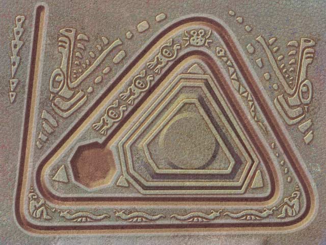
So let’s start with this “triangle” level. The background picture of this level is this:

triangle

So i’m expecting the .dat file describing a curve matching the picture. Opening the file with a hex editor presents me with the following content:

hxd_1

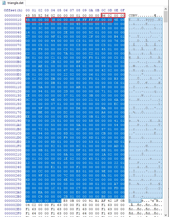
By simply eye balling on the hex digits, i can tell it has a header of 16 bytes (first row), which seems to be the following structure:

typedef struct
{
char signature[4];
uint32_t unk1, unk2;
uint32_t size;
} header_t;

the “size” field is the one i’m particularly interested in, as it outlines the first section of the level data.  Looking into the binaries, and i realized, the data begins with a “count”, and then a group of element of length of 10 bytes.  Let’s say it’s a structure of the following:

type def struct
{
uint32_t x;
uint32_t y;
uint16_t unk;
} elem_t;

I don’t know if i’m guessing it correctly, so let’s try plotting the data out. I’m using python notebook for this task:

plot_1

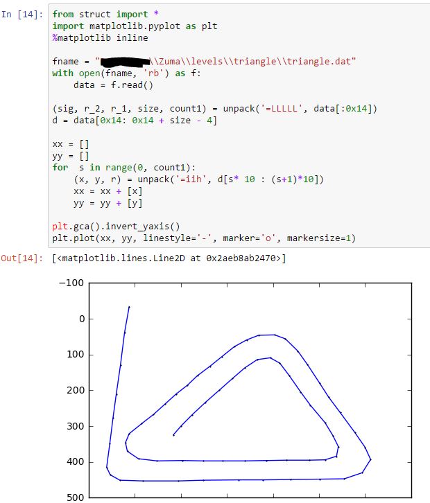
Bingo! It matches what I was guessing! When i was doing this, the first element was confusing me for quite a while as it as a negative “y” coordinate. So i skipped the first element. Later I tried to explain to myself with the first element, and found it makes sense, as the curve starts out side of the screen. So, mystery solved! Well, not completely, as there is a unknown “short” field.

Anyway, i was eager to try this out, so I altered a couple points, and tried to load the level in game, expecting something strange will happen. But nothing! The game ran as usual if it were not changed.

So what’s going on? I realized that I only had first section of the level file decoded, not entire file. What’s left?

So here is the second section. Following the logic of the first section, the first 4 bytes look like another “size” field, but doesn’t quite match.

hxd_2

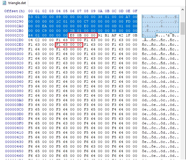
Anyway, let’s continue. After a couple strange numbers, the rest all the way to the end of file is something like a list of integers, with a slowly changing values. First i tried to plot them as (x, y) pairs, but that didn’t come up very well.  I don’t know what i was thinking, but i somehow, plotted the first two bytes of each 4-byte group, as “x,y” pairs, and it looks like this:

plot_2

Yes! This is definitely something! But how can a circle of dots relate to a curved track? Anyway, i started messing around with those data, and found:

  1. As long as being consistent with the header, changing the 1st section doesn’t make any visual differences. I even tried replace the entire section to a zero sized stub, the game still runs very well.
  2. Replacing the second section with that of other level file makes the game changes completely. It’s like i’m using this level’s background picture, but with the other level’s track.

These findings make me really thinking that the first section is not used at all. Then, how does the second section define the curve?

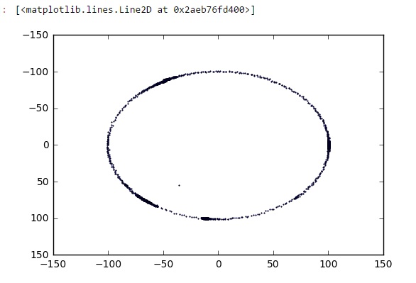
I was scratching my head for more than an hour while my son kept bugging me with all sorts of weird things. Then suddenly, i got the point! It can be an array of “delta_x, delta_y” for the points on the track!

To verify that, i did the following plotting. Again, the first couple bytes are strange so I skipped them:

plot_3

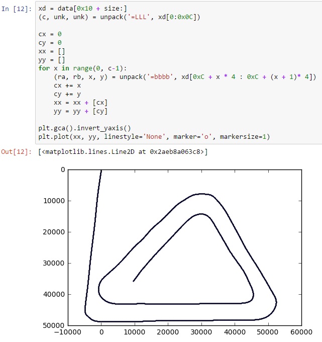
Fantastic! This proves my theory! Now all i need is to figure out two things:

  1. right scale, apparently the image i got is in very wrong scale
  2. origin, i’m expecting something between 640×480, and the first point should be something consistent as the value defined in first section

The first one is easy, looking at the current range, i think all i need is to divide the cx, cy by 100. The second one took me a couple seconds, by looking into the strange bytes at the beginning of the section:

 91 B1 AF 42 1F 0B 04 C2

Again, if i were to design this game and storing all the deltas, the first point should be somewhere. As we mentioned section 1 is not used at all, so this must be in section two, which leaves only these bytes. But their value doesn’t look like integers at all!

I almost instantly know what i should be looking into: floating points!  If i’m storing the deltas by a scale of 100, i probably want to divide them by 100. Storing the coordinates using 100 times of the actual coordinates on screen would be a good idea.

So that makes the following complete code:

plot4

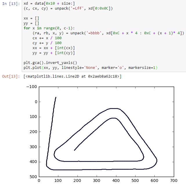
Mission accomplished!

So what’s next? Maybe a custom Zuma level designer?


Posted in computer games, programming, reverse engineering | Tagged , , , , | 10 Comments

TI Stellaris launchpad with IAR EWM — where do my printf messages go

Last week while cleaning up old stuff, I found two TI Stellaris (they now renamed it to Tiva) launchpad development kits in my junk box. I guess I bought them when TI firstly released them and then completely forgot. They are great ARM development kits for beginners. I happen to have a work related project based on ARM Cortex M4 so I think it’s time to try them to get familiar with ARM embedded development. Instead of using TI’s CCS, I’m choosing IAR EWM simply because I don’t like Eclipse based IDEs.

As many other developers do, my first program will be a “Hello World” (well, blinking LED is another type of “Hello World” for embedded world, but I just found getting debug message is always more important than blinking things in real life). Things have gone really well when I finished the single line “printf(“Hello World!\n”)” in main.cpp, and then I started looking into project settings trying to find out where the default IAR runtime will output the result. I’m sure there will be someway redirecting the stdio from target uC to  host PC, it’s just hiding somewhere.

My first bet was the “Debug Log” pane, however, i was wrong, nothing showed up there. And then googling/binging/… until more than 10 minutes later, I finally found the answer:

First make sure your project is having stdout/stderr implemented “via semihosting” — This is the default option, but I changed it when I was trying to figure out where the message has gone :

000020

And this option is only available when you are in debugging mode:

000021

Here is the lovely “Hello World” message:

000022

OK. I hope this can save you some effort if you just started playing with the kit:)

Posted in Uncategorized | Leave a comment

Hacking a Dell power adapter — final (not really)

!!! WARNING: With this project, you power adapter will be reporting false information which may not match the original design. This may cause severe results such as file or damaging your laptop. Do it on your own risk!!!


As I mentioned in my previous post, there are at least two ways fixing the unidentified power adapter issue, and I chose the hard way, which is simulating how DS2502 works using a micro controller. This is all about learning one wire protocol and I did learnt a lot. I think the most important thing is timing, with a uC working at 16Mhz or 8Mhz, you need to carefully counting how many cycles your interrupt routine takes and providing the logical level in time.  And different optimization results between release vs debug configuration also needs to be taken into account.

Anyway, I sort of finished the project with something left not fully implemented. Here is the source code and pcb design. I also made the PCB by hand using toner-transfer method. It’s a great chance to learn the whole process from coding, PCB design, and PCB making…

Here are some pictures:

schematic:

Image

pcb layout:

Image

Final result:

Image

Image

Image

To proof it’s working, I successfully faked my 90W adater to 65W:

WP_20140225_012 WP_20140225_013

I was trying to make it display some weird wattage numbers but found dell may have some white-list and so far any wattage not 90W or 65W will not be recognized.

There are still unfinished things including importing the data from a working power adapter, storing multiple data and switching between them. I have all the hardware components ready but don’t have time finishing the software part yet, which should be pretty straight forward, except my limited RAM (128 bytes) and flash spaces (4KB).

Anyway, a good opportunity to learn one wire protocol with this project. The PCB design and code can be found at https://github.com/HclX/DELL_POWER_SPOOFER.git


Posted in MSP430 | Tagged , , | 33 Comments